2008-08-31

Photosynth Export Process Tutorial

It looks like I have unofficial recognition/support for my export process, but I get the feeling it's still too user unfriendly:

http://getsatisfaction.com/livelabs/topics/pointcloud_exporter


What to do

Get Wireshark http://www.wireshark.org/

Allow it to install the special software to intercept packets.

Start Wireshark. Put

http.request

into the filter field.

Quit any unnecessary network activity like playing youtube videos- this will dump in a lot of data to wireshark that will making finding the bin files harder.

*** Update ***
Some users have found the bin files stored locally in %temp%/photosynther, which makes finding them much easier than using Wireshark, but the for me on Vista the directory exists for one user but not others- but the bin files have to be stored locally somewhere right?
***

Open the photosynth site in a browser. Find a synth with a good point cloud, it will probably be one with several hundred photos and a synthiness of > 70%. There are some synths that are 100% synthy but have point clouds that are flat billboards rather than cool 3D features- you don't want those. Press p or hold ctrl to see the underlying point cloud.

*** Update ***
Use the direct 3d viewer option to view the synth, otherwise you won't get the synth files. (thanks losap)
***

Start a capture in Wireshark - the upper left butter and then click the proper interface (experiment if necessary).

Hit reload on the browser window showing the synth. Wireshark should then start show ing what files are being sent to your computer. Stop the capture once the browser has finished reloading. There may be a couple screen fulls but near the bottom should be a few listings of bin files.
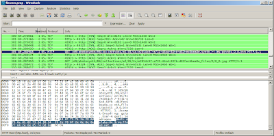


Select one of the lines that shows a bin file request, and right-click and hit Copy | Summary (text). Then in a new browser window paste that into the address field. Delete the parts before and after /d8/348345348.../points_0_0.bin. Look back in Wireshark to discover what http address to use prior the that- it should be http://mslabs-nnn.vo.llnwd.net, but where nnn is any three digit number. TBD- is there a way to cut and paste the fully formed url less manually?

If done correctly hit return and make the browser load the file- a dialog will pop up, save it to disk. If there were many points bin files increment the 0 in the file name and get them all. If you have cygwin a bash script works well:

for i in `seq 0 23`
do
wget http://someurl/points_0_$i.bin
done


Python

Install python. If you have cygwin installed the cygwin python with setup.exe, otherwise http://www.python.org/download/ and download the windows installer version.
*** UPDATE *** It appears the 2.5.2 windows python doesn't work correctly, which I'll look into- the best solution is to use Linux or Cygwin with the python that can be installed with Linux ***

Currently the script http://binarymillenium.googlecode.com/svn/trunk/processing/psynth/bin_to_csv.py works like this from the command line:

python bin_to_csv.py somefile.bin > output.csv


But I think the '>' will only work with cygwin and not the windows command prompt. I'll update the script to optionally take a second argument that is the output file.

If there are multiple points bin files it's easy to do another bash loop to process them all in a row, otherwise manually do the command above and create n different csvs for n bin files, and then cut and paste the contents of each into one complete csv file.

The output will be file with a long listing of numbers, each one looks like this:

-4.17390823, -1.38746762, 0.832364499, 24, 21, 16
-4.07660007, -1.83771312, 1.971277475, 17, 14, 9
-4.13320493, -2.56310105, 2.301105737, 10, 6, 0
-2.97198987, -1.44950056, 0.194522276, 15, 12, 8
-2.96658635, -1.45545017, 0.181564241, 15, 13, 10
-4.20609378, -2.08472299, 1.701148629, 25, 22, 18


The first three numbers are the xyz coordinates of a point, and the last three is the red, green, and blue components of the color. In order to get a convention 0-255 number for each color channel red and blue would have to be multiplied by 8, and green by 4. The python script could be easily changed to do that, or even convert the color channels to 0.0-1.0 floating point numbers.

Point Clouds - What Next?
The processing files here can use the point clouds:
http://binarymillenium.googlecode.com/svn/trunk/processing/psynth/

Also programs like Meshlab can use them with some modification- I haven't experimented with it much but I'll look into that and make a post about it.

2008-08-28

Color Correction


I have the colors figured out now: I was forgetting to byteswap the two color bytes, and after that the rgb elements line up nicely. And it's 5:6:5 bits per color channel rather than 4 as I thought previously, thanks to Marvin who commented below.

The sphinx above looks right, but earlier the boxer shown below looked so wrong I colored it falsely to make the video:


The Boxer - Photosynth Export from binarymillenium on Vimeo.

But I've fixed the boxer now:


The python script is updated with this code:


bin.byteswap()
red = (bin[0] >> 11) & 0x1f
green = (bin[0] >> 5) & 0x3f
blue = (bin[0] >> 0) & 0x1f

2008-08-27

Exporting Point Clouds From Photosynth


Since my last post about photosynth I've revisited the site and discovered that the pictures can be toggled off with the 'p' key, and the viewing experience is much improved given there is a good point cloud underneath. But what use is a point cloud inside a browser window if it can't be exported to be manipulated into random videos that could look like all the lidar videos I've made, or turned into 3D meshes and used in Maya or any other program?

Supposedly export will be added in the future, but I'm impatient like one of the posters on that thread so I've gone forward and figured out my own export method without any deep hacking that might violate the terms of use.

Using one of those programs to intercept 3D api calls might work, though maybe not with DirectX or however the photosynth browser window is working. What I found with Wireshark is that http requests for a series of points_m_n.bin files are made. The m is the group number, if the photosynth is 100% synthy then there will only be one group labeled 0. The n splits up the point cloud into smaller files, for a small synth there could just be points_0_0.bin.

Inside each bin file is raw binary data. There is a variable length header which I have no idea how to interpret, sometimes it is 15 bytes long and sometimes hundreds or thousands of bytes long (though it seems to be shorter in smaller synths).

But after the header there is a regular set of position and color values each 14 bytes long. The first 3 sets of 4 bytes are the xyz position in floating point values. In python I had to do a byteswap on those bytes (presumably from network order) to get them to be read in right with the readfile command.

The last 2 bytes is the color of the point. It's only 4-bits per color channel, which is strange. The first four bits I don't know about, the last three sets of 4 bits are red, blue, and green. Why not 8-bits per channel, does the photosynth process not produce that level of precision because it is only loosely matching the color of corresponding points in photos? Anyway as the picture above shows I'm doing the color wrong- if I have a pure red or green synth it looks right, but maybe a different color model than standard rgb is at work.

I tried making a photosynth of photos that were masked to be blue only- and zero synthiness resulted - is it ignoring blue because it doesn't want to synth up the sky in photos?

Anyway here is the python script for interpreting the bin files.

The sceneviewer (taken from the Radiohead sceneviewer) in that source dir works well for displaying them also.

Anyway to repeat this for any synth wireshark needs to figure out where the bin files are served from (filter with http.request), and then they can be downloaded in firefox or with wget or curl, and then my script can be run on them, and processing can view them. The TOC doesn't clearly specify how the point clouds are covered so redistribution of point clouds, especially those not from your own synths or someone who didn't CC license it, may not be kosher.

2008-08-24

More python pcap with pcapy

After running into pcap files several hundreds of megabytes in size that caused wireshark to crash when loaded, I returned to trying to make python work with the source pcap file:


import pcapy

vel = pcapy.open_offline('unit 46 sample capture velodyne area.pcap')

vel
Reader object at 0xb7e1b308

pkt = vel.next

pkt
built-in method next of Reader object at 0xb7e1b308


What is a Reader object, and a built-in method of it? Why are the addresses the same?

try

pkt = vel.next()

type(vel)
type 'tuple'

vel[1]


'\xff\xff\xff\xff\xff\xff\x00\x00\x00\x00\x00\x00\x08\x00E\x00\x04\xd2
\x00\x01\x00\x00\x80\x11\xad\x9f\xc0\xa8\x03+\xc0\xa8\x03\xff\x01\xbb
\t@\x04\xbe\x00\x00\xff\xddz\x13\xee
...
\x00\x00\x10\xd63Md\xc2\xff\x00\x00\x0fp\x07v25b'


So that's just the problem I was running into before: '\xff' is an ascii representation of binary data that's really 0xff. But I'm given it in ascii- I can't index into this and get a specific 8-bit 0-255 binary value, I get a '\'. Do I have to write something that goes through this and reinterpets the ascii-ized hex back into real hex?

Also I note the ff dd that marks the beginning of the data frame is there but not at the beginning- so there are other parts of the packet here I need to get rid of. Is this where I need Impacket?

import impacket
from impacket.ImpactDecoder import EthDecoder

decoder = EthDecoder()
b = decoder.decode(a)
Traceback (most recent call last):
File "stdin", line 1, in ?
File "/var/lib/python-support/python2.4/impacket/ImpactDecoder.py", line 38, in decode
e = ImpactPacket.Ethernet(aBuffer)
File "/var/lib/python-support/python2.4/impacket/ImpactPacket.py", line 340, in __init__
self.load_header(aBuffer)
File "/var/lib/python-support/python2.4/impacket/ImpactPacket.py", line 255, in load_header
self.set_bytes_from_string(aBuffer)
File "/var/lib/python-support/python2.4/impacket/ImpactPacket.py", line 59, in set_bytes_from_string
self.__bytes = array.array('B', data)
TypeError: an integer is required

oops

b = decoder.decode(a[1])
print b
Ether: 0:0:0:0:0:0 -> ff:ff:ff:ff:ff:ff
IP 192.168.3.43 -> 192.168.3.255
UDP 443 -> 2368

ffdd 7a13 ee09 3cbe 093f 1811 2b1f 1020 ..z.....?..+..
0a0a 63ac 0848 d708 53ea 085b 0000 1bc0 ..c..H..S..[....
0a35 0c09 425b 0936 000d 2e44 0d2f 120b .5..B[.6...D./..
4f5e 0b30 200f 3c4e 0e50 c30b 46c7 0b4d O^.0 .

The decode makes a nice human readable text of the packet, but not what I want.

Here is a different tack- by looking in the Impacket.py source I found how to do this which converts that annoying ascii back to real bytes, which is the only real issue:

mybytes = array.array('B', vel[1])

mybytes is of size 1248, so there appear to be 42 extra bytes of unwanted ethernet wrapper there- why not just index into mbytes like mybytes[42:] and dump that to a binary file?

I don't know about the dumping to binary file (print mybytes prints it in ascii, not binary)- but I could easily pass that array straight into the velodyne parsing code- and this skips the intermediate file step, saving time and precious room on my always nearly full laptop hd.

So here is the final result, which produce good CSVs I was able to load with my 'velosphere' Processing project to create 360 degree panoramas from the lidar data:

Next I need a way to write pngs from python, and I could eliminate the CSVs & Processing step.

2008-08-23

Photosynth

When I first saw the original demo I was really impressed, but now that is been released I feel like it hasn't advanced enough since that demo to really be useful. I tried a few random synths when the server was having problems, it looks like it isn't being hammered any longer so I ought to try it again soon when I'm using a compatible OS.

Overall it's confused and muddled to use and look at- like a broken quicktime VR.

Photosynth seems to work best in terms of interface and experience when it is simply a panoramic viewer of stitched together images- where all the images are taken from a point of buildings or scenery around the viewer. It's easy to click left or right to rotate left or right and have the view intuitively change. But we've had photostitching software that produces smooth panoramas that look better than this for years, so there's nothing to offer here.

When viewing more complicated synths, the UI really breaks down. I don't understand why when I click and drag the mouse the view rotates to where I'd like, but then it snaps back to where it used to be when I let go of the button. It's very hard to move naturally through 3D space- I think the main problem is that the program is too photo-centric: it always wants to feature a single photograph prominently rather than a more synthetic view. Why can't I pull back to view all the photos, or at least a jumble of outlines of all the photos?

It seems like there is an interesting 3D point cloud of points found to be common to multiple photos underlying the synth but it can't be viewed on it's own (much less downloaded...), there are always photos obscuring it. The photograph prominence is constantly causing nearby photos to become blurry or transparent in visually disruptive ways.

Finally, it seems like the natural end-point of technology like this is to generate 3D textured models of a location, with viewing of the source photos as a feature but not the most prominent mode. Can this be done with photosynth-like technology or is all the aspects I don't like a way of covering up that it can't actually do that? Maybe it can produce 3D models but they all come out horribly distorted (so then provide a UI to manually undistort them).

Hopefully they will improve on this, or another well-backed site will deliver fully on the promise shown here.

2008-08-20

Makeavi


Discovered a neat windows (and vista) tool for turning image sequences into videos: http://makeavi.sourceforge.net/


1280x720 in the 'Microsoft Video 1' format worked well, though 57 MB of pngs turned into 135 MB of video. 'Uncompressed' didn't produce a video just a small 23kb file. 'Intel IYUV' sort of produced a video but not correctly. 'Cinepak' only output a single frame. 'VP60 Simple profile' and 'VP61 Advanced Profile' with the default settings worked, and actually produces video smaller than the source images, though quicktime player didn't like those files. Vimeo seems to think VP61 is okay:


More Velodyne Lidar - overhead view from binarymillenium on Vimeo.

This new video is similar to the animated gifs I was producing earlier, but using a new set of data. Vimeo seems to be acting up this morning, I got 75% through an upload of the entire file (the above is just a subset) and it locked up. I may try to produce a shorter test video to see if it works.

I have around 10 gigs of lidar data from Velodyne, and of course no way to host it.

My process for taking pcap files and exporting the raw data has run into a hitch- wireshark crashes when trying to 'follow udp stream' for pcap files larger than a couple hundred megabytes. Maybe there is another tool that can do the conversion to raw?

2008-08-14

Phase Correlation for Lidar Image Alignment


After going through the manual alignment of the point cloud data noted in the last post, I've gotten the translation step of automatic alignment using phase correlation.

Phase correlation requires the use of a 2d fft, which I couldn't find in Processing (would have to bring in a java lib for that somehow?). Instead I used Octave, which has the fft2, inverse ifft2 function, and many other convenient math functions. The Matlab/Octave file is here.

The fundamental phase correlation code is this:

a = imread('one.png')
b = imread('two.png')

af = fft2(a);
bf = fft2(b);

% cross power
cp = af.*conj(bf) ./ abs(af.*conj(bf));

icp = (ifft2(cp));

mmax = max(max(icp));
[sx,sy,v] = find(mmax == icp);


And sx and sy are the translation to apply to b to make it line up with image a. An additional check is to make sure the largest value in icp is above some threshold- if it is lower than the threshold then there is no good translation to align the data.

I'm a little suspicious that my input pngs are too regular and easy, every frame seems a constant displacement from the former as the vehicle with the lidar was moving at a constant velocity.

Rotation is mostly working in isolation but I need to revisit the proper method to make simultaneous rotation and translation work- there was a paper somewhere I need to dig up.

2008-08-11

Point Cloud Alignment


I took about 1/5th of the png images generated from the Velodyne point cloud data and manually aligned them in Gimp. It's easy to shift-select a bunch of images and open them as individual layers in Gimp, but there are no multiple layer selection capabilities: it's not possible for instance select all the layers and change their transparency.

In all of the images there are a few features, mostly beyond the edges of the road, that can be aligned with the earlier and later images. The closer together the images are in time the easier this is, but I was skipping every 4 images to take the 5th in order to speed up the process- also a gimp image with 300 layers is difficult to handle.

The later portions of the data are all purely translational, only at the very beginning are rotations and translations needed.

I think an automatic process for alignment won't be that hard, but the inherent inconsistency in frame to frame image will make for a lot of error. Translations correspond to phase shifts in the frequency domain, and I think rotations are almost as simple- and there isn't any scaling to account for.

2008-08-07

Dorkbot Cacophony


The theme is catastrophic cacophony and the challenge is to build the loudest, craziest, flashiest automated "musical" instrument ever. You will have to be able to step back and let your creation play by itself, even if it destroys itself in the process.


This event was a lot of fun, I helped build a sort of guitar that gets strummed by a motor. With a little more time I think we could have made it less repetitive by add another motor to move the first one back and forth or up and down.

Other teams had things that sounded like higher frequency wind-chimes, or just pure noise.


Dorkbot Cacophony from binarymillenium on Vimeo.

2008-08-03

Animated gif of height map

animated gif of height map

Source code is here:

http://code.google.com/p/binarymillenium/source/browse/#svn/trunk/processing/velodyne

One interesting thing I discovered is that animated gifs with an alpha channel don't just let the back ground of the web page show through, they also don't clear the last frame of the gif- which was confusing for this gif before I blackened the background with ImageMagick:

for i in *png; do convert $i -background black -flatten +matte flat_$i; done
convert flat*png velodyne_hgt.gif

Velodyne Lidar Sample Data

Applying the db.xml calibration file

As with the pcap parsing, I originally thought I'd look into Python xml parsing. I'm sure if I was really interested in parsing xml I would have tried some of them out, but the interface I was hoping to find would look like this


import pyxmlthing
a = pyxmlthing.load("some.xml")
some_array= a.item('9').rotCorrection


And I would have an array of all the rotCorrections of all the items of type 9. Instead I found a several xml parsers that required tons of code to get to a point where I'm still not sure if I could get at the rotCorrections or not. Which may be why I don't care for xml, flat-files are it.

So I just used vim to strip all the xml out and leave me with a nice text file that looks like this


0, -3.8, -7.0046468, 20, 21.560343, -2.5999999
1, -1.5, -6.7674689, 26, 21.516994, 2.5999999
2, 5, 0.44408101, 28, 20.617426, -2.5999999
3, 6.8000002, 0.78093398, 32, 20.574717, 2.5999999


Where the first column is the laser index (0-63), the next might be the rotCorrection and so on.

To apply the calibration data, it's very important that the indexing derived from the raw data is correct- reading the 0xDDEE vs. the 0xDDFF (or similar) that designates upper or lower laser block is important.

The velodyne manual doesn't have a good diagram that shows the xyz axes and what is positive or negative direction for both the original lidar angle and the correction angles and offsets, so some experimentation is necessary there. The manual did mention it in this case the rotCorrection had to be subtracted from the base rotation angle. The vertical and horizontal offset are pretty minor for my visualization but important for accurate measurements obviously.


Processing viewer

Using Aaron Koblin's House of Cards SceneViewer as a starting point, I wrote code to take the point cloud data and display it:


Monterey Full from binarymillenium on Vimeo.

The data was split into files each containing a million data points and spanning a second in time. With some testing I found the lidar was spinning at about 10 Hz (of the possible 5, 10, or 15 Hz), so I would bite off 1/10 of the file and display that in the current frame, then the next 1/10th for the next frame, and then load the next file after 10 frames. A more consistent approach would be to split the data into a new text file for each frame.

Next Steps

Right now I'm running a large job to process each point-cloud frame into png height-map files as I did for the Radiohead data. It doesn't work as well with the 360 degrees of heights- some distances just have to be cut off and ignored to keep the resolutions low (although with the png compression having large empty spaces doesn't really take up any additional room). A lot of detail is lost on the nearby objects compared to a lot of empty space between distant objects.

So either using that data or going back to processing the raw point cloud, I'd like to track features frame-to-frame and derive the vehicle motion from them. I suspect this will be very difficult. Once I have the vehicle motion, I could create per-frame transformations that could create one massive point cloud or height map where still objects are in their proper places and other vehicles probably become blurs.

After that, if I can get a dataset from Velodyne or another source where a moving ground lidar moves in a circle or otherwise intersects its own path somewhere, then the proof that the algorithm works will be if in that big point cloud that point of intersection actually lines up. (though I suspect again that more advanced logic is need to re-align the data after the logic determines that it has encounter features that it has scene before).